


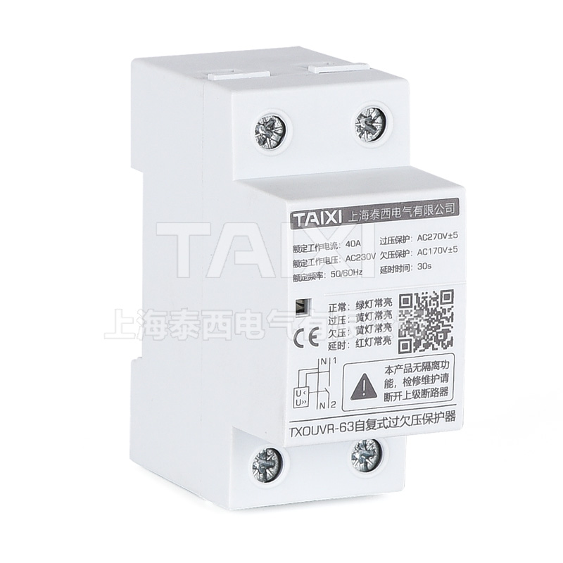
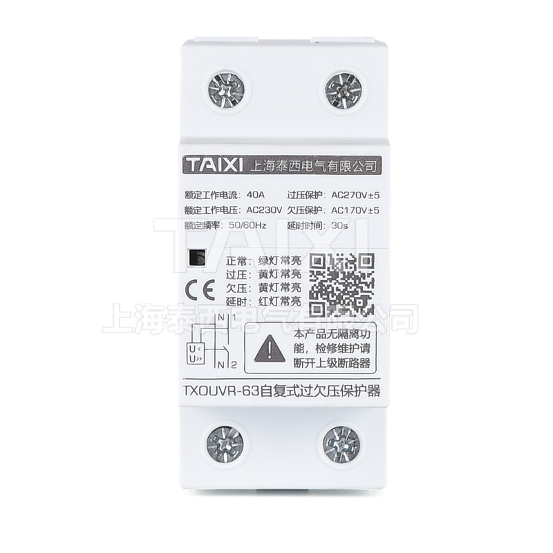


TXOUVRD-63 Voltage Protector
Miniature Circuit Breaker | MCB


Parameters
Details
Size&weight
Related
Video
Message
SCOPE OF APPLICATION
TXOUVR self-resetting over-voltage and under-voltage delay protector is also known as automatic reset over-voltage and under-voltage protector. It is suitable for current or load with single-phase AC voltage of 220V, frequency of 50Hz, and rated working current of 60A and below. As the protection of single-phase electrical equipment against single-phase line over-voltage and under-voltage caused by neutral line fault. It is mainly used for the protection of the incoming line of the residential sub-box or the protection of the distribution line that needs to protect the single-phase electrical equipment.
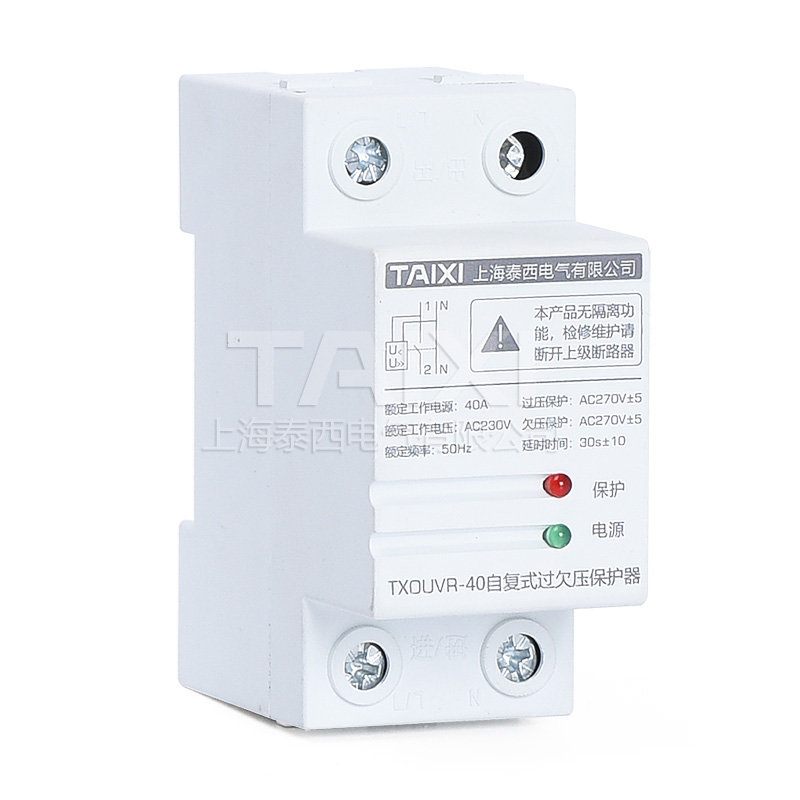
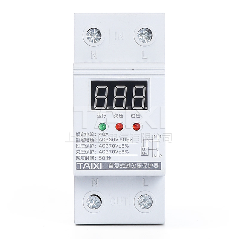
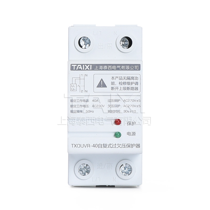
The width of TXOUVR self-replicating over-voltage and under-voltage delay protector is 36mm wide. The control current is quite convenient for installation in the distribution box. The control circuit board is assembled with imported components. The product is produced with modular standards, with excellent performance and reliability. It can work normally under abnormal voltage conditions. When the mains voltage exceeds the set overvoltage action voltage value of the protector or is lower than the undervoltage action voltage value of the protector, the protector can cut off the circuit quickly and reliably to protect the safety of electrical appliances. When the mains voltage returns to normal, the protector can automatically delay the power connection and restore the power supply, and all functions are automatically implemented without human operation. The light-emitting diodes on the panel can indicate the working status of the protector. The green light of the indicator light is the indication of the working power supply. When the red light of the indicator light is off, the power supply is normal. When the red light is on, the protection function starts to cut off the power supply. The self-resetting overvoltage and undervoltage protector has a compact structure, beautiful appearance, and the installation is common to the DZ47 (C45) guide rail.
DESIGN PRINCIPLE
The control circuit of the automatic reset overvoltage and undervoltage protector adopts high-speed micro-low power consumption processor as the core, magnetic latching relay as the main circuit, and modular standard design. When there is overvoltage or undervoltage in the power supply line, the protector can Quickly and safely cut off the circuit under continuous high-voltage shocks to avoid accidents caused by abnormal voltage being sent to the terminal electrical appliances. When the voltage returns to normal, the protector will automatically turn on the circuit within a specified time to ensure that the terminal electrical appliances are unattended. normal operation.
FEATURES
When the single-phase line is over-voltage and under-voltage, the line is cut off, and the single-phase line voltage returns to normal after a delay, and the line is automatically reset and connected, without manual operation. When transient or transient overvoltage occurs on the line, the protector will not malfunction.
The protector does not connect the line when the voltage is unstable due to faults such as unrealistic contacts, or when the power is suddenly cut off and then a call is made suddenly.
When the line fault voltage is the highest, the protector itself will not be damaged.
The protector has an inverse time limit action characteristic, and the action time is less than or equal to 1s.
Voltage protection range: 0~450V below 40A, 50/60A: 0~600V.
Withstand impulse voltage: 4kV (in line with the safety standards of Class III electrical appliances).
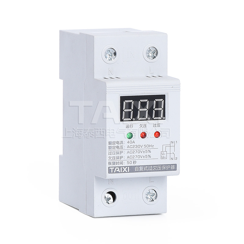
The protector has two-color light-emitting diodes to indicate the working state, green - normal voltage indicator; red - overvoltage or delay indicator.
Installation method: 35mm rail type installation, appearance modular design.
Wiring capacity: 1P+N: 25mm² and below insulated wire, 3P+N: 35mm² and below insulated wire
Comply with the standard: "Code for Design of Civil Buildings" JGJ-242 2011 Edition
Ambient temperature: -5℃~40℃;
Altitude: no more than 2000m;
Humidity: When the maximum temperature of the installation site is 40°C, the relative humidity of the air does not exceed 50%. Higher relative humidity is allowed at lower temperatures, such as 90% at 20°C. Special measures should be taken for the occasional condensation due to temperature changes;
THE MAIN TECHNICAL PARAMETERS
| Operating Voltage | AC 220V | AC 380V |
| Rated current ln (A) | 40A, 60A, 80A, 100A | |
| Working frequency | 50/60Hz | |
| Load power | 8.8kw, 13.2kw,17.6kw, 22kw | 15.2kw,22.8kw,30.4kw,38kw |
| Overvoltage action cut-off value | AC 270±5V | AC 460V±15V |
| Overvoltage recovery value | AC 255±5V | each phase AC255±5V |
| Undervoltage action cut-off value | AC 170±5V | AC 300V±15V |
| Undervoltage recovery value | AC 185±5V | each phase 185±5V |
| Power delivery delay | 30±10s / 60±10s | 60±10s |
| Action delay time | ≤1s | |
| Own power consumption | ≤2W | |
| Electrical and mechanical life | ≥100,000 | |
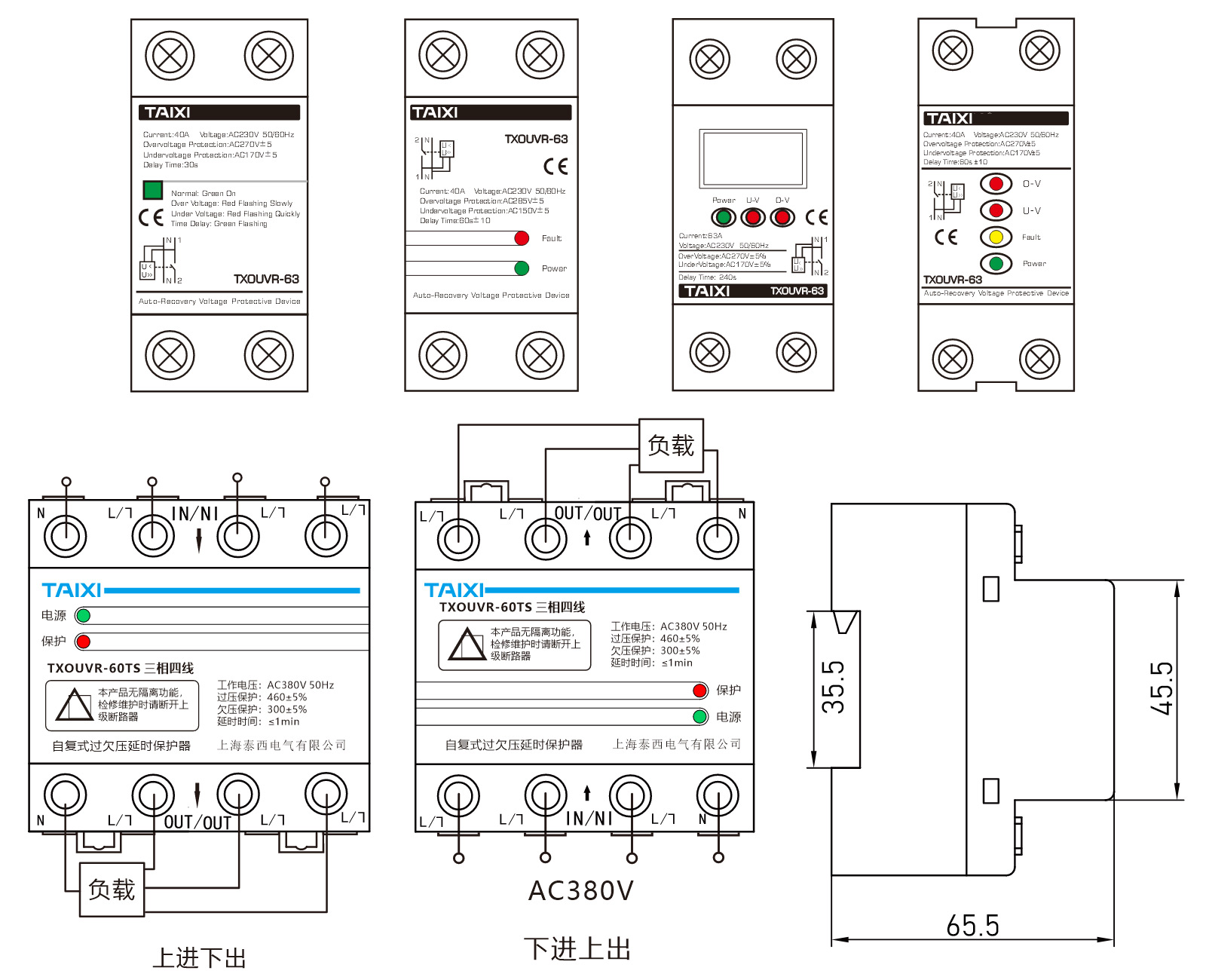
| Connection method | Upper Input Lower Output / Lower Input Upper Output | |
OUTLINE DIMENSIONAL DRAWING
INSTRUCTIONS FOR USE
1. Correctly connect the input terminal (IN) and output terminal (OUT) according to the product identification (the load power should be less than the rated power of the product).
2. The two-color light-emitting tube on the panel of the self-reversing overvoltage and undervoltage protector indicates the status: after the product is powered on, the light-emitting tube glows red, the OUT terminal has no output power, and after the delay protection 1min~2min, it glows green. The OUT terminal normally outputs power.
3. The two light-emitting tubes on the panel of the self-resetting overvoltage protector for the upper incoming line indicate the status: after the product is powered on, the protection indicator is red, and the OUT has no output power. After the delay protection is 1min~2min, the output indicator is green. , OUT normal output power.
4. When overvoltage or undervoltage occurs, the product enters the protection state, the red light is on, and the load power supply is automatically cut off; when the voltage returns to normal, after a delay of 1min~2min, the green light is on, the product automatically turns on the load power supply and returns to the normal output state.
PRECAUTIONS
1. When the input terminal of the product is connected to the power supply for the first time, it needs to delay 1min~2min to supply power to the load.
2. Product wiring: N is zero wire, L is live wire, please do not connect wrongly.
3. After the product is powered on, do not touch the live parts to avoid electric shock.
4. In order to prevent the contact from heating under strong current, be sure to tighten the screws of the terminal when wiring, otherwise the product will be damaged or other accidents will be caused due to excessive contact resistance, which will cause heat at the terminal.
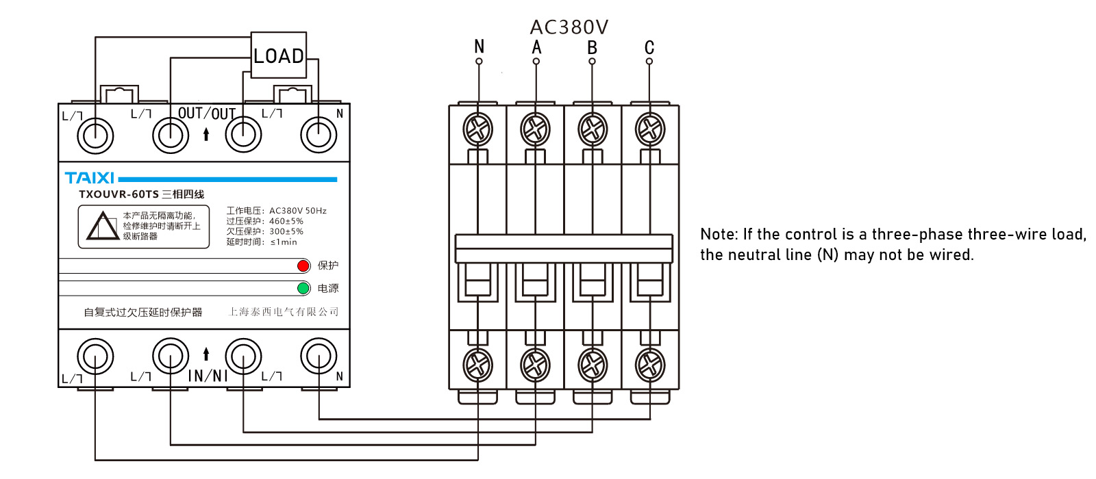
APPLICATION CIRCUIT EXAMPLE (GO DOWN AS AN EXAMPLE)
The protector controls a three-phase four-wire load. When the power consumption does not exceed the rated capacity of the controller, the direct control method can be used. The wiring method is shown in the figure below.
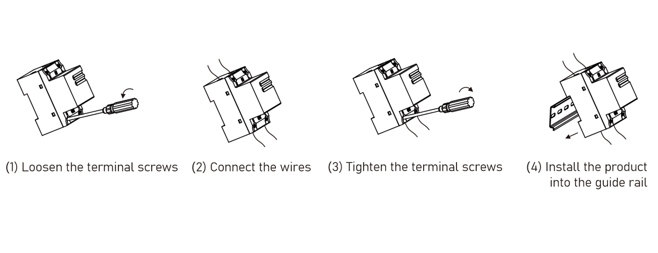
INSTALLATION METHOD
Note: The main circuit power must be cut off before installation or removal

view and download
| File name(Click to view) | File type | file size | View times | Click to download |
Product related news
| News title | Promulgator | Release time | View times | Click to read |