


HR6 Switch Disconnector Fuse Unit
Isolation Switch


Parameters
Details
Size&weight
Related
Video
Message
Scope of application
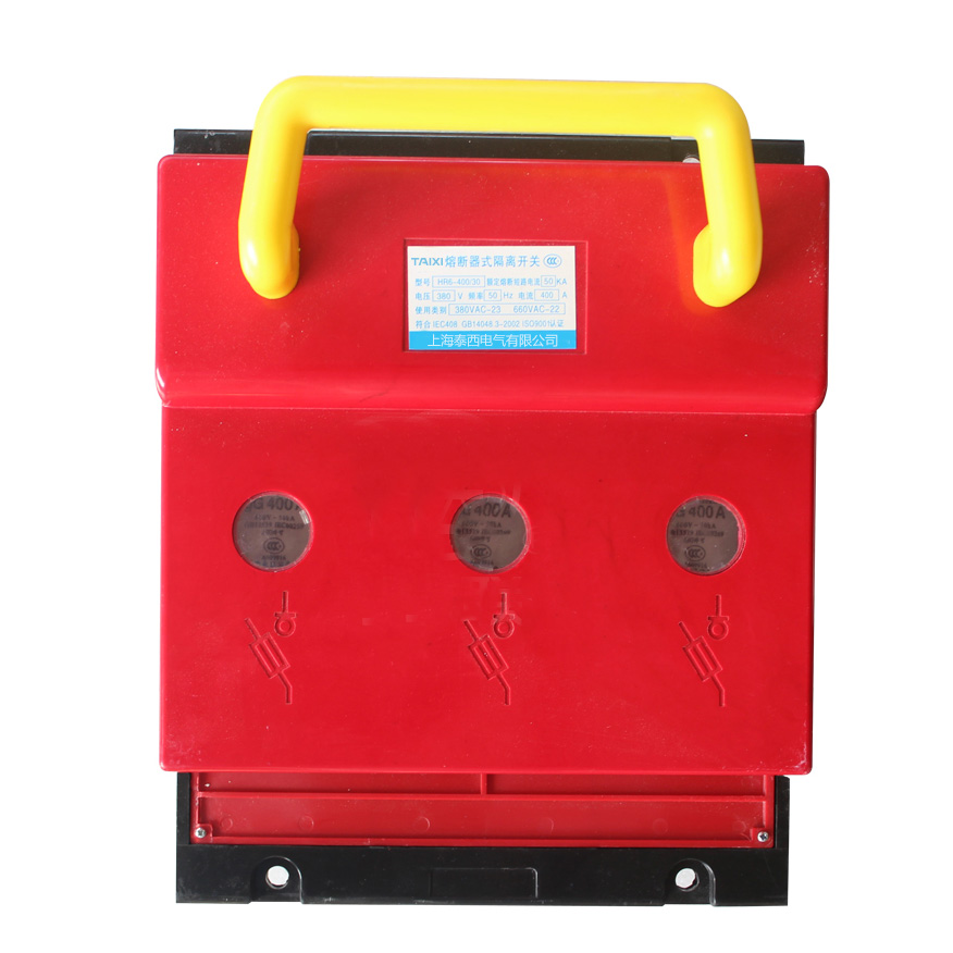
HR6 Switch Disconnector Fuse Unit (hereinafter referred to as switch) is mainly used as power switch, Switch Disconnector, emergency switch in the distribution circuit and motor circuit with high short circuit current, rated voltage AC 400V and 660V (45~62Hz), conventional thermal current to 800A, and for circuit protection. But it does not normally open or close a single motor directly. The Switch Disconnector Fuse Unit conforms to the IEC60947-3, GB14048.3.
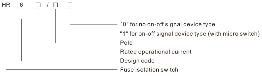
Model and meaning
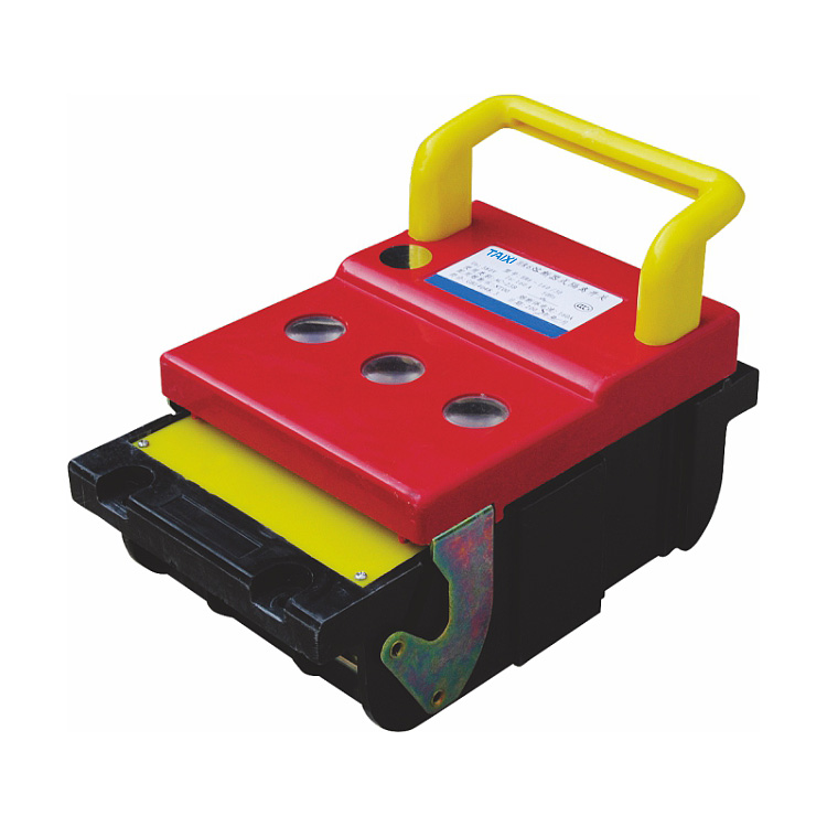
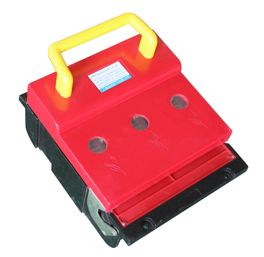
Structure characteristics
The Switch Disconnector Fuse Unit consists of a base, a cover, an arc chute and others, all of which are made of arc-resistant plastic and are all-plastic structures. The static contact is directly installed on the base, and the arc chute is easy to disassemble and install. Each arc chute has two parts, the inner chamber and the outer chamber, and uses a plurality of metal arc extinguishing grids to enhance the arc extinguishing ability and improve the contact life.
The NT type fuse link is mounted in the cover, and the cover can rotate along the support member in a fan-shaped manner, and has a large electrical isolation distance to meet the requirements of the isolating switch. The cover can be easily detached from the base, so that it is very easy to install and replace the fuse link. Convenience. There are two sets of mounting holes on the base to meet the requirements for installation in various switch cabinets and panels. On both sides of the switch, auxiliary contact can be installed as required, and sends out signals indicating the on-off state of the switch.
Main parameters and technical performance
The relationship between the switch and the fuse (see Table 1)
Main Technical ParametersThe auxiliary switch's rated voltage is AC 400V, conventional thermal current is 6A, the use category is AC-15, and the rated control capacity is 300VA.
Normal working conditions
1. The ambient air temperature is not higher than +40°C and not lower than -5°C.
2. The elevation of the installation site does not exceed 2000m.
3. Humidity: When the maximum temperature is +40°C, the relative humidity of the air does not exceed 50%, and higher relative humidity may be allowed at lower temperatures, for example, 90% at 20°C. Special measures should be taken for the occasional condensation caused by temperature changes.
4. The pollution level of the surrounding environment is 3.
5. The Switch Disconnector Fuse Unit shall be installed in a place where there is no significant shaking, shock and vibration and there is no rain and snow. At the same time, there shall be no dangerous medium for explosion at the installation site, and there shall be no gas and dust in the medium that can corrode metal and destroy insulation.
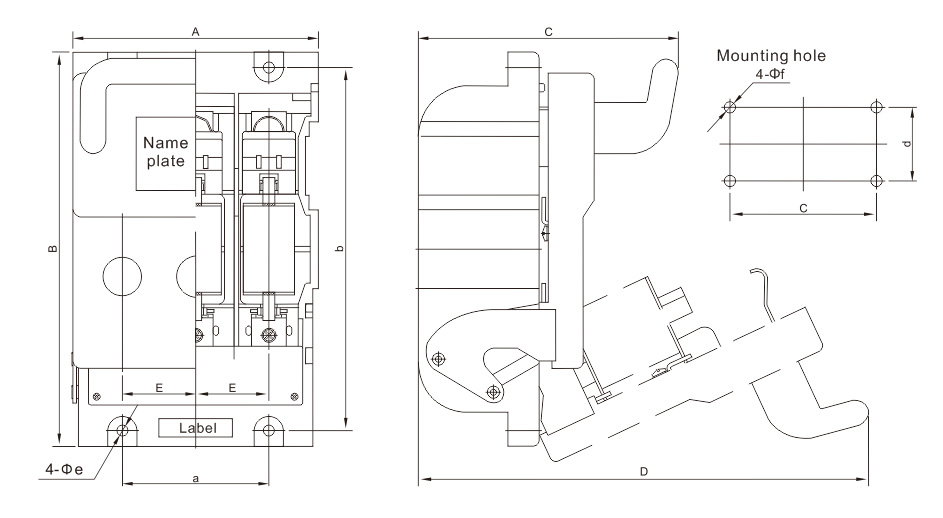
Outline and Installation Dimensions

view and download
| File name(Click to view) | File type | file size | View times | Click to download |
Product related news
| News title | Promulgator | Release time | View times | Click to read |