


Parameters
Details
Size&weight
Related
Video
Message
Scope of application
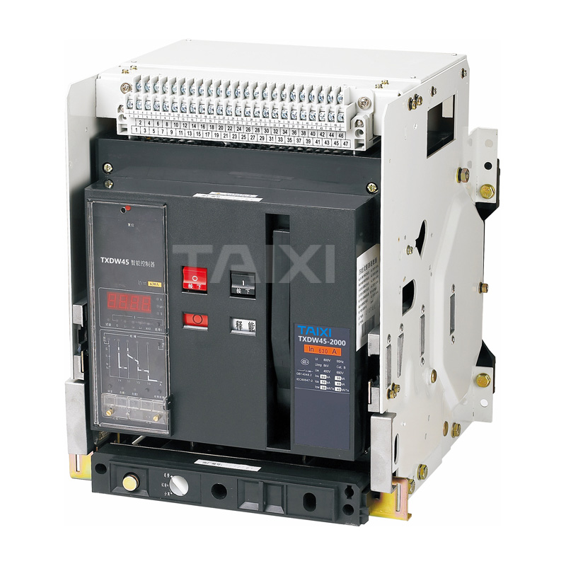
DW45 Air Circuit Breaker, ACB (hereinafter referred to as circuit breaker) is suitable for distribution network with AC 50Hz, rated voltage to 660V (690V) and below, the rated current 630A~6300A, used to distribute power and protect line and power equipment from overload, undervoltage, short circuit, single-phase grounding and other faults. Air Circuit Breaker have intelligent protection function, selective protection is precise, can improve power supply reliability and avoid unnecessary power outages. At the same time, it has an open communication interface to carry out "Four Remotes" to meet the requirements of the control center and automation system. The circuit breaker has an impulse withstand voltage of 8000V at 2000 meters (revised at different altitudes, not exceeding 12000V). The acb air circuit breaker are not equipped with intelligent controller and sensor, and can be used as isolator.
TAIXI is a professional air circuit breaker manufacturers The acb air circuit breaker meets the GB14048.2 "Low-voltage switchgear and controlgear Low-voltage circuit breakers" and IEC60947-2 "Low-voltage switchgear and controlgear circuit breakers" and other standards.
Model and meaning

Model and meaning
● Classification
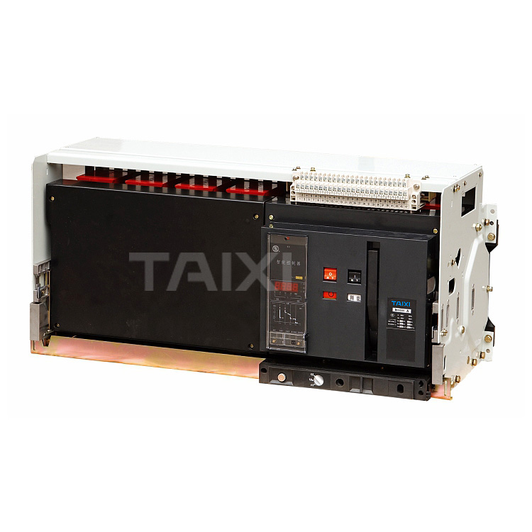
According to the installation method: fixed type, drawer type.According to the poles: three poles, four poles. According to the operating mode: electric operation, manual operation (overhaul, maintenance).
● Release type
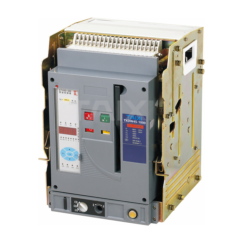
Intelligent controller, under-voltage transient (or delay) release, shunt release.● Intelligent controller performance
a. The intelligent controller of Air Circuit Breaker is divided into: bse5 (H type: communication), bse4 (M type: common intelligent type), bse3 (L type: economic type);b. With overload long delay inverse time limit, short delay inverse time limit, definite time limit, instantaneous function. Users can set their own required protection characteristics;
c. Single-phase grounding protection function;
d. Display function: setting current display, operating current display, main display of each phase voltage (voltage display should be put forward when ordering);
e. Alarm function: overload alarm;
f. Self-check function: overheating self-check, microcomputer self-diagnosis;
g. Test function: Test the operating characteristics of the controller.
Normal working conditions and installation conditions
● Ambient air temperature: The upper limit value does not exceed +40°C, the lower limit value is not less than -5°C, and the average value in 24h does not exceed +35°C.
Note: The working condition is that lower limit value is -10°C or -25°C, the user should declare with the company; The upper limit exceeds +40°C or the lower limit is lower than -10°C or -25°C working conditions, users should consult with the company.
● The altitude of the installation site does not exceed 2000m.
● Atmospheric conditions of Air Circuit Breaker: Atmospheric relative humidity does not exceed 50% when the ambient air is +40°C. It can have relatively high relative humidity at lower temperatures. The monthly average maximum relative humidity of the wetest month is 90%. The average minimum temperature is +25°C and consider the condensation that occurs on the product surface due to temperature changes. Exceed the required requirements and consult with the company.
● Protection level: IP30
● Pollution level: III
● Use category: Class B or Class A
● Installation category: acb air circuit breaker and undervoltage release with rated operating voltage of 660V (690V) or less. The primary coil of the power transformer is used for installation category IV. The installation category of the auxiliary circuit and control circuit is III.
● Installation conditions: The circuit breaker shall be installed in accordance with the requirements of this manual. The vertical inclination of the circuit breaker shall not exceed 5° (the inclination of the mine circuit breaker shall not exceed 15°).
Brief introduction of structure
● The positive indication of the circuit breaker


Technical data and performance
● Rated current of circuit breaker
● Rated short-circuit breaking capacity and short-time withstand current, the circuit breaker's arc distance is zero (that is, no arcing outside the circuit breaker).
Note: The breaking capacity of the upper and lower lines in the table is the same● Protection characteristics and functions of intelligent overcurrent controller
Protection characteristics of overcurrent controller1. The setting value Ir (I/In) and error of the controller
Note: When there is (required) three-stage protection at the same time, the setting values cannot be crossed.
2. Long-delay overcurrent protection inverse-time operation characteristics I²TL=(1.5lr1)²tL, and the operation time of (1.05~2.0)lr1 is shown in Table 4, and the time error is ±15%.
Note: tL-Long delay 1.5lrs setting time, TL-Long delay operation time.
Note: When there is (required) three-stage protection at the same time, the setting values cannot be crossed.
3. Short delay over-current protection characteristics
Short-time delay over-current protection is definite time limit. If the low multiple is required to be inverse time, the characteristic is: I²Ts=(8Ir1)²ts, ts is the general delay design time;
When the overload current >8Ir, it automatically converts to the definite time characteristic. Its definite time limit characteristic is shown in Table 5. The time limit error is ±15°C.
| Delay time s | Returnable time s | ||||||
| 0.1 | 0.2 | 0.3 | 0.4 | 0.06 | 0.14 | 0.23 | 0.35 |
Wiring Diagram of Circuit Breaker
1. Wiring diagram of L, M type intelligent controller (standard type) (see Figure 1)

SB1 - Shunt button (user-supplied)
SB2 - Undervoltage button (user-supplied)
F - Shunt release
O - Normally Open Contact (3A/AC380V)
C - Normally closed contact (3A/AC380V)
Q - Undervoltage instantaneous release or undervoltage delay release
M - Energy storage motor
SB3 - Closing button (user-supplied)
X - Closing electromagnet
DF - Circuit breaker auxiliary contact
1# Work power input end (DC module for positive input)
2# Work power input end (DC module for negative input)
25#, 26# External center pole or ground current transformer input
19#, 20#, 21#, 22#, 23#, 24# are Frame II and III adding contacts.
3# Fault trip, normally closed contact output
4# Fault trip, contact output common end
5# Fault trip, normally open contact output
* When the power supply for the intelligent release is DC power supply, the power supply module must be added. (1# and 2# terminals are prohibited from accessing the AC power supply).
2. Wiring diagram of M, H intelligent controller + additional function (multi function) (see Figure 2)

SB1 - Shunt button (user-supplied)
SB2 - Undervoltage button (user-supplied)
F-Shunt release
O-Normally Open Contact (3A/AC380V)
C- Normally closed contact (3A/AC380V)
Q - Undervoltage instantaneous release or undervoltage delay release
M - Energy storage motor
SB3 - Closing button (user-supplied)
X - Closing electromagnet
DF - Circuit breaker auxiliary contact
1#, 2# Output power input
3#, 4#, 5# Fault trip contact output
And 4# line is public end
6#, 7# Breaker status first auxiliary contact output end
8#, 9# Breaker status second auxiliary contact output end
10# Communication interface outlet A end
11# Communication interface outlet B end
12#, 13# First signal contact output end
14#, 15# Second signal contact output end
16#, 17# Third sets of signal contact output end
18#, 19# Fourth sets of signal contact output end
20# Protection ground line
21# N phase voltage input end
22# A phase voltage input end
23# B phase voltage input end
24# C phase voltage input end
25# External transformer input end 1
26# External transformer input end 2
Outline and Installation Dimension
● Outline and installation dimension of DW45-2000(FrameⅠ) Fixed Air Circuit Breaker

● Outline and installation dimension of DW45-3200 (FrameⅡ) Fixed Circuit Breaker

● Outline and installation dimension of DW45-2000(FrameⅠ) Drawer ACR Air Circuit Breaker

● Outline and installation dimension of DW45-3200(Frame Ⅱ) Drawer Air Circuit Breaker

● Outline and installation dimension of DW45-4000(Frame Ⅱ Increase capacity) Drawer ACR Air Circuit Breaker

● Outline and installation dimension of DW45-4000/4(FrameⅠ3+4 type) Drawer ACR Air Circuit Breaker

● Outline and installation dimension of DW45-6300/4000A~5000A (Frame Ⅲ) Drawer ACR Air Circuit Breaker

● Outline and installation dimension of DW45-6300/3 6300A (Frame Ⅲ) Drawer ACR Air Circuit Breaker

● External connection copper specifications, quantity

view and download
| File name(Click to view) | File type | file size | View times | Click to download |
Product related news
| News title | Promulgator | Release time | View times | Click to read |