


TXCM1Z Molded Case Circuit Breaker
Solar Disconnect Switch


Parameters
Details
Size&weight
Related
Video
Message
SCOPE OF APPLICATION
TXCM1Z Molded Case Circuit Breaker (16A~250A, 225A~400 amp or 400 amp~ 630A DC Circuit Breaker, PV DC MCCB) is used for low-voltage power generation, transmission and distribution lines of rated voltage of DC500V, 750V and 1000V, rated current of 16A~250A, 225A~400 amp or 400 amp~ 630A to provide isolation, overload and short circuit protection, DC MCCB can also be used for infrequent making and breaking of circuits under normal circumstances.
The DC MCCB are widely used in photovoltaic power generation systems, wind power generation systems, roof building power generation systems, rail transit power distribution systems and infrastructure construction and other low-voltage DC generation, transmission and distribution application occasions.
TWO RELEASE METHODS
| Protection function | Frame size | Rated current In (A) | Short-circuit protection current setting Ir (A) |
Operation time |
| Operation time | TXCM1Z-250 | 16-250 | 10In | Instantaneous operation |
| TXCM1Z-400 | 225-400 | 10In | ||
| TXCM1Z-2630 | 400-630 | 10In | ||
| Operating tolerance | ±20% | |||
Thermal + electromagnetic release
| Protection function | Frame size | Rated current In (A) | Short-circuit protection current setting Ir (A) |
Operation time |
| Operation time | TXCM1Z-250 | 16-250 | 10In | Instantaneous operation |
| TXCM1Z-400 | 225-400 | 10In | ||
| TXCM1Z-2630 | 400-630 | 10In | ||
| Operating tolerance | ±20% | |||
| Protection function | Protection function | Rated current In (A) | Operating characteristics |
| Overload protection | All series | 16~630 | According to I²t operation 1.05In (Cold), no operation within 1h (In≤63A) 1.3In (Hot), ≤1h operation (In≤63A) 1.05In (Cold), no operation within 2h (In>63A) 1.3In (Hot), ≤2h operation (In>63A) |
ALTITUDE
●Altitude of TXCM1Z DC MCCB installation place in normal work is not more than 2000m.
●If you need to install it at an altitude of more than 2000m, which can be used according to the altitude factor derating table.
Derating factor of altitude corresponds to the circuit breaker
| Altitude (m) | 2000 | 3000 | 4000 | 5000 |
| Rated frequency withstand voltage | U | U | U | U |
| Max operating voltage | Ue | Ue | Ue | Ue |
| Rated operating current | ln | 0.97In | 0.93In | 0.89In |
TEMPERATURE
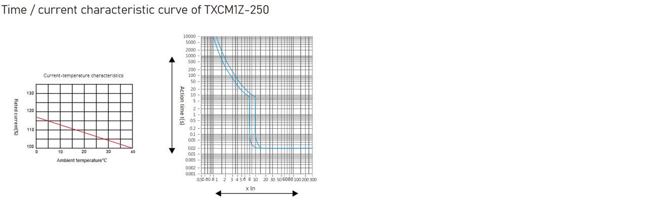
●Can be used in the lowest temperature of -25℃, the highest temperature of +40℃.
●If they need to work at less than -25℃ or higher than +40℃, you can use them according to temperaturecompensation factor table.
●Consult with the manufacturer when using at less than -25℃ or more than +40℃.
Ambient temperature changes in the temperature compensation factor table
| Ambient temperature Coefficient Model |
+40℃ | +45℃ | +50℃ | +55℃ | +60℃ |
| Derating factor | Derating factor | Derating factor | Derating factor | Derating factor | |
| -250 | 1In | 0.96In | 0.96In | 0.87In | 0.82In |
| -400 | 1In | 0.94In | 0.87In | 0.81In | 0.73In |
| -630 | 1In | 0.93In | 0.88In | 0.83In | 0.76In |
Note: The above derating factors are measured at current value equal to the frame rated current
HUMIDITY
● In the ambient air temperature of +40℃, atmospheric relative humidity can not exceed 50%, if the temperature is low, you can use it under high humidity conditions.
● The monthly average relative humidity of the wettest month is 90%, and the effect of condensation on the productsurface should be considered.
STANDARDS AND CERTIFICATION
| International standard | International standard | |
| Product standard | G | |
| IEC 60947-1 (General rules) | G | B 14048.l |
| IEC 60947-2 (Circuit breaker) | G | B 14048.2 |
| IEC 60947-3(Switch, Isolation) | G | B 14048.3 |
| Extreme environmental test standard | National standard | |
| Extreme environmental test standard | G | B/T 2423.l |
| IEC 60068-2-2 | G | B/T 2423.2 |
| IEC 60068-2-11 | G | B/T 2423.17 |
| IEC 60068-2-30 | G | B/T 2423.4 |
MAIN TECHNICAL PARAMETERS
| Model of circuit breaker | TXCM1Z-250 | TXCM1Z-400 | TXCM1Z-630 | ||||
| Frame rated current (A) | 250 | 400 | 630 | ||||
| Electrical performance | |||||||
| Pole (P) | 3 | 4 | 3 | 4 | 3 | 4 | |
| Rated current In (A) | 16/20/25/32/40/SOI 63/80/100/125/140/ 160/180/200/2251250 |
225/250/315/350/400 | 400/500/630 | ||||
| Rated insulation voltage Ui (V) | 1000 | 1000 | 1000 | ||||
| Rated impulse voltage Uimp (V) | 8000 | 8000 | 8000 | ||||
| Rated operating voltage Ue (V) | DC500 | DC750 | DC500 | DC750 | DC500 | DC750 | |
| DC750 | DC1000 | DC750 | DC1000 | DC750 | DC1000 | ||
| DC1000 | ≤50 | ≤100 | ≤100 | ||||
| Rated ultimate short-circuit breaking capacity Icu (kA) |
DC500 | 65 | - | 65 | - | 65 | - |
| DC750 | 40 | 50 | 40 | 50 | 40 | 50 | |
| DC1000 | - | 40 | - | 40 | - | 40 | |
| Rated operating short-circuit breaking capacity Icu(kA) |
DC500 | 100%Icu | - | 100%Icu | - | 100%Icu | - |
| DC750 | 50%Icu | 100%Icu | 50%Icu | 100%Icu | 50%Icu | 100%Icu | |
| DC1000 | - | 50%Icu | - | 50%Icu | - | 50%Icu | |
| Rated short-circuit making capacity Icm (kA) |
100%Icu | 100%Icu | 100%Icu | ||||
| Use category | A | A | A | ||||
| Electrical life (times) | 5000 | 1000 | 1000 | ||||
| Mechanical life (times) | Maintenance-free | 10000 | 5000 | 5000 | |||
| Have maintenance | 20000 | 10000 | 10000 | ||||
| Connection and installation | |||||||
| Outline dimensions (mm) | Width (3P/4P) | 107/142 | 150/198 | 182/240 | |||
| Length | 165 | 257 | 270 | ||||
| Height | 104.5 | 104.5 | 108.5 | ||||
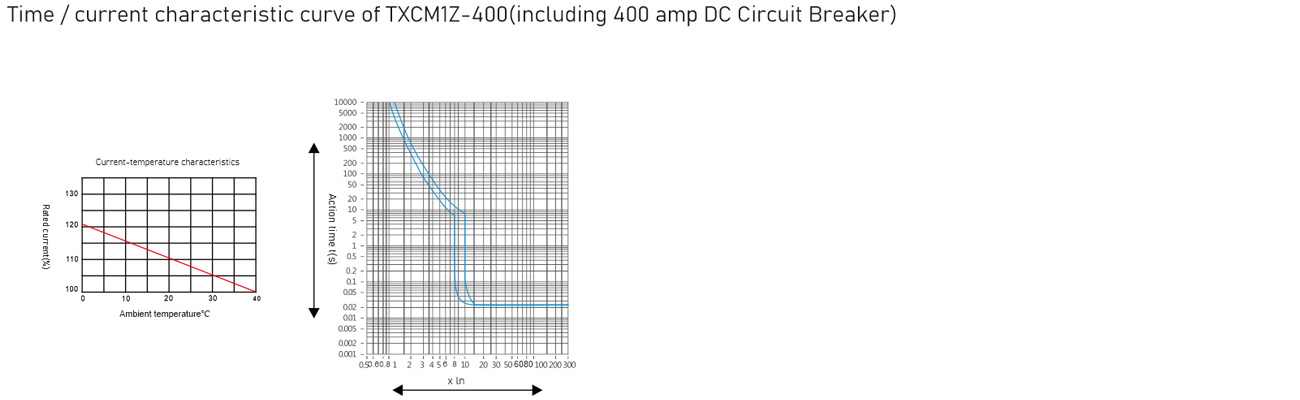
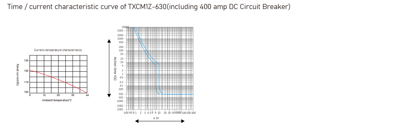
TIME / CURRENT CHARACTERISTIC CURVE
WIRING MODE
Different power system / load wiring mode
| Rated operating voltage | Power / load wiring mode | ||||||||
| Ungrounded system | Negative grounded system | ||||||||
| DC500 | E | - | - | - | E | - | - | - | - |
| DC750 | E | - | - | - | - | - | - | - | |
| DC1000 | - | - | - | H | - | - | - | H | H |
Note: (1) In the negative grounded system, the wiring must be according to the above table.
(2) In the ungrounded system and the neutral point grounded system, use the wiring on the table. User pagecan exchange the positive and negative based on the actual situation, but also can exchange wiring positionof the power supply and load.
DC SYSTEM APPLICATIONS
Choosing circuit breakers in a DC system need to mainly consider the following aspects:
● Rated operating voltage, consider the breaking poles in series
● Rated current, consider the load power
● Breaking capacity, consider the max short-circuit current at the installation point
| System type | Grounding system | Ungrounded system | ||
| Negative grounding | Negative grounding | |||
| Various fault types | ||||
| Fault effect | Fault 1 | Produce maxshort-circuit current,contact connecting to the positivepole of the power supplyis off | U/2 voltage produces the nearest max short-circuit current,contact connecting to the positive pole of the power supply is off | No effect |
| Fault 2 | Produce max short-circuit current, but the contacts in series are broken | Produce max short-circuit current, but the contacts in series are broken |
Produce max short-circuit current, but the contacts in series are broken |
|
| Fault 3 | Produce max short-circuit current, but the contacts in series are broken | The same as the fault I, but only for contacts connecting to the negative pole of the power supply |
No effect | |
| The worst situation | Fault I | Fault I and II | Fault II | |
| Breaking poles situation | Can be connected to the positive pole in series, carry out the breaking together | For every pole,carry out the breaking of the maximum short-circuit current at U/2 |
The poles carry out the breaking together |
|
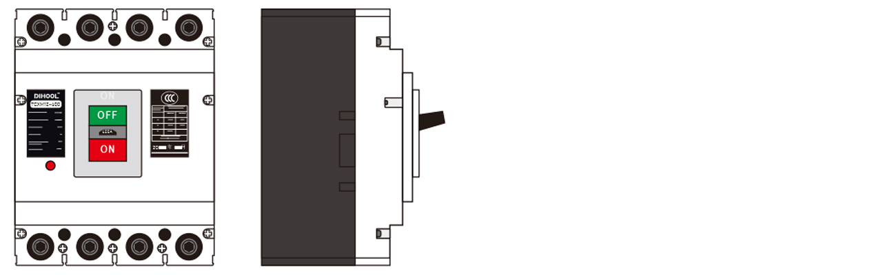
OUTLINE AND INSTALLATION DIMENSION
| Type/Installation location / Poles / Accessory name |
TXCM1Z-250 | TXCM1Z-400 | TXCM1Z-630 | |||
| 3P | 4P | 3P | 4P | 3P | 4P | |
| Nothing | - | - | - | |||
| Shunt release |  |
|
|
|||
| Auxiliary contact |  |
|
|
|||
| Undervoltage release |  |
|
|
|||
| Shunt release Auxiliary contact |  |
|
|
|||
| Shunt release Undervoltage release |  |
|
|
|||
| Two sets of auxiliary contact |  |
|
|
|||
| Undervoltage release Auxiliary contact Auxiliary contact |  |
|
|
|||
| Alarm contact |  |
|
|
|||
| Shunt release Alarm contact |  |
|
|
|||
| Auxiliary contact Alarm contact |  |
|
|
|||
| Undervoltage release Alarm contact |  |
|
|
|||
| Shunt release Auxiliary+Alarm contact |  |
|
|
|||
| Two sets of auxiliary contact Alarm contact |  |
|
|
|||
| Undervoltage release Auxiliary+Alarm contact |  |
|
|
|||
QUICK SIZING
The cross-sectional area of the TXCM1Z connecting wire and the corresponding rated current
| Rated current (A) | 10 | 16 12 | 25 | 32 | 40 50 | 63 | 80 | 100 | 125 140 | 160 | 180 200 225 | 250 | 315 350 | 400 |
| Wire sectional area (mm²) | 1.5 | 2.5 | 4 | 6 | 10 | 16 | 25 | 35 | 50 | 70 | 95 | 120 | 185 | 240 |
| Rated current (A) | Cable | Copper bar | ||
| Sectional area (mm²) | Quantity | Size mmxmm | Quantity | |
| 500 | 150 | 2 | 30×5 | 2 |
| 630,700 | 185 | 2 | 40×5 | 2 |
| 800 | 200 | 2 | 40×5 | 2 |
OUTLINE AND INSTALLATION DIMENSIONS

view and download
| File name(Click to view) | File type | file size | View times | Click to download |
Product related news
| News title | Promulgator | Release time | View times | Click to read |