


Parameters
Details
Size&weight
Related
Video
Message
Product Overview
TXR1-700 Soft Starter for AC three phase Motor is a new start-up equipment which integrates electric force and electron techniqus, computer technique and modern control theory. It is the new generation product to replace the conventional star-delta starter, self-coupling voltage-drop starter and magnetic control voltage-drop starter; Its performance is unmatched by most of the Motor Soft Starter products that do not adopt multiple closed loop control technology in the market at present.
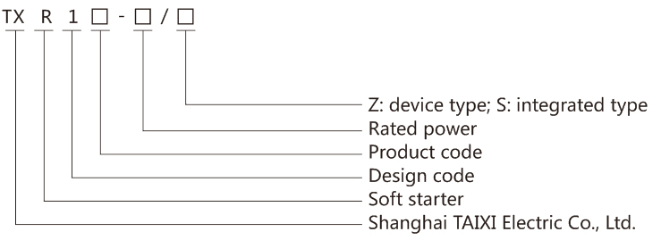
Model and Meaning
Main Function
1. This Motor Soft Starter can reduce the starting current of the motor and the power-distribution capacity to motor effectively and avoid the grid capacity investment.
2. Reduce the starting stress of the motor and load equipment; Lengthen the service life of the motor and related equipment.
3. The Motor Soft Starter stop function effectively solves the surge problem of the inertia system; The conventional motor starting equipment can not realize it.
4. With six unique start modes; to meet complex motor and load conditions for perfect start-up.
5. With perfect and reliable protection function; it effectively protects the safety of the motor and related production equipment.
6. The application of intelligent and network technology make the Motor Soft Starter meet the high speed devolpment of electrical force automation technology effectively.
7. Perfect humanized design: beautiful appearance and reasonable structure, perfect function and simple operation, firm and reliable structure, and artistic design with perfect industrial products.
8. Reliable quality assurance: computer simulation design, SMT production process, excellent electromagnetic compatibility performance, high temperature aging and vibration test before delivery.
9. Perfect and reliable protection functions: voltage loss, undervoltage, overvoltage protection, Motor Soft Starter overheating, long starting time protection, input phase loss, output phase loss, three-phase unbalance protection, starting overcurrent, running overload, load short circuit protection.
Use Environment and Conditions
Power supply: City power, self-supplied power, diesel oil dynamotor, three-phase alternating current AC 380V or 660V±15%, rated frequency 50Hz or 60Hz, power supply capacity to the Motor Soft Starter must meet starting requirements for the motor.
Motor matched: squirrel-cage three-phase asynchronous motor, the rated power of the motor should match the rated power of the Motor Soft Starter.
Starting frequency: No requirement, the specific number depends on the load.
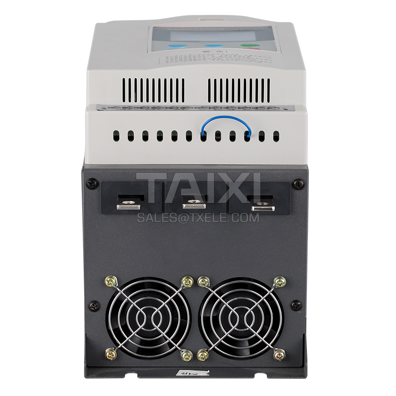
Cooling method: natural wind cooling.
Protection level: IP20.
Environmental conditions: Altitude is less than 1000m, ambient temperature is between 0°C~+40°C, relative humidity is less than 90%RH, no vapor, no flammable, volatilee, corrosive gas, no electric dirt, indoor ventilation, ventilated, the vibration is less than 0.5G.
Products that can be used in special conditions, such as explosion-proof, low-temperature, high-voltage Motor Soft Starter. The use conditions are explained separately.
Motor matched: squirrel-cage three-phase asynchronous motor, the rated power of the motor should match the rated power of the Motor Soft Starter.
Starting frequency: No requirement, the specific number depends on the load.
Cooling method: natural wind cooling.
Protection level: IP20.
Environmental conditions: Altitude is less than 1000m, ambient temperature is between 0°C~+40°C, relative humidity is less than 90%RH, no vapor, no flammable, volatilee, corrosive gas, no electric dirt, indoor ventilation, ventilated, the vibration is less than 0.5G.
Products that can be used in special conditions, such as explosion-proof, low-temperature, high-voltage Motor Soft Starter. The use conditions are explained separately.
Installation Requirements
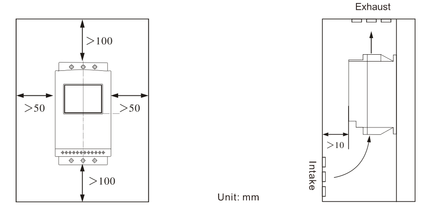
The direction and distanceof installation: In order to make sure that the Motor Soft Starter be in good draft and heat dissipation conditions during use, please install the Motor Soft Starter in vertical direction, and be sure the space around the equipment is enough. When the Motor Soft Starter is installed in the cabinet, please note that the draft is very good, as well as the above notes.
Outline and lnstallation Dimension
Outline and lnstallation Dimension of TXR1-700 Soft Starter for AC three phase Motor 5.5kW~75kW, 6-inlet and 3-outlet
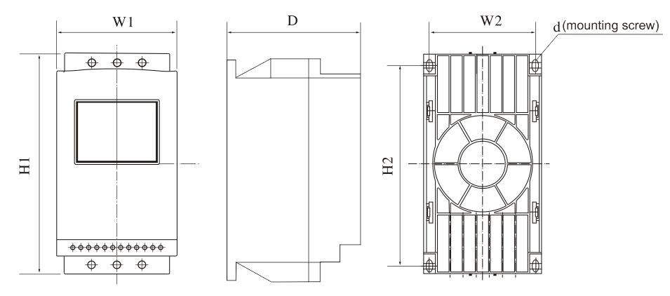
Note: Rated power of motor in the above form is the Max rated value, generally, the values of matched motor should not be more than this value.
Outline and lnstallation Dimension of TXR1-700 Soft Starter for AC three phase Motor 75kW~560kW, 6-inlet and 3-outlet
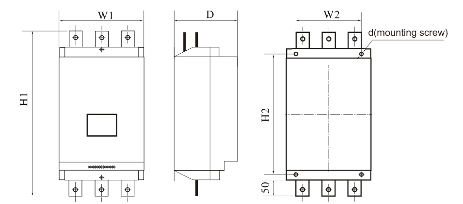 Note: Rated power of motor in the above form is the Max rated value, generally, the values of matched motor should not be more than this value.
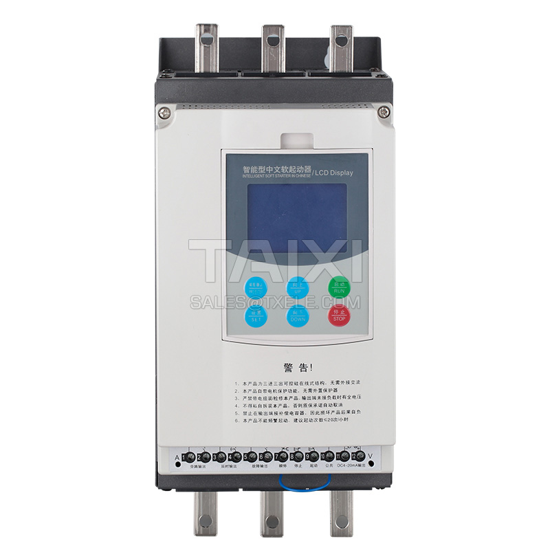
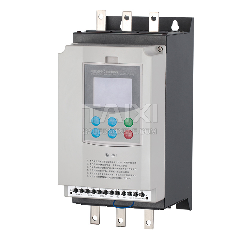
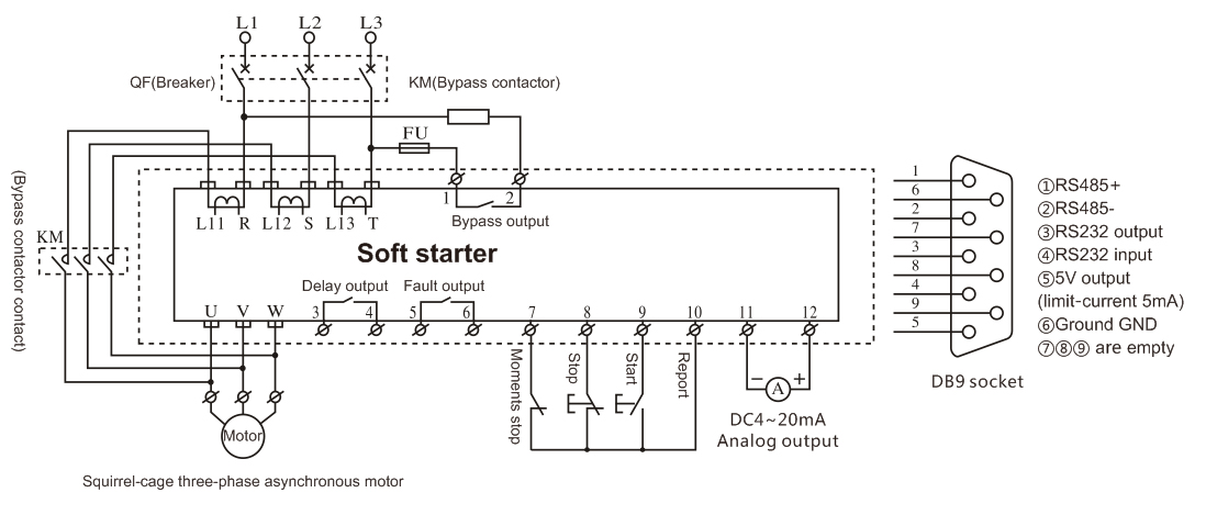
Wiring and external terminal
TXR1-700 Soft Starter for AC three phase Motor has three types of wirings, as following:
Main circuit wiring: it contains the wiring of 3-phase source input and output to the motor, and the bypass contactor wiring.
Wiring of external terminal: the wire comes from 12 external terminals which including input-output control signal lines and analogue output signal lines.
Communication wiring: RJ-45 standard web line socket and DB9 socket are used to connect the computer or the computer network.
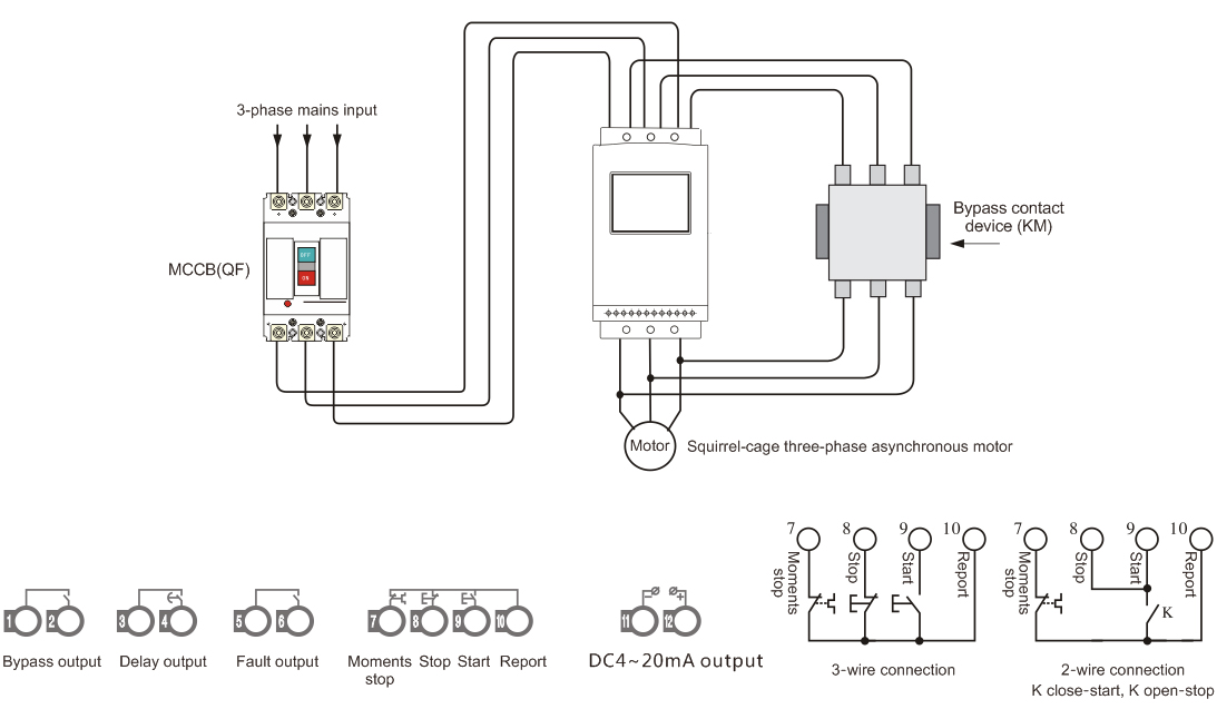
Terminals ① ② are bypass outputs: used to control the bypass contactor, which are the normally open passive contact and are closed when finishing starting. Contact capacity is AC250V/5A.
Terminals ③ ④ are programmable relay outputs: the delay time is set by F4, and the output time is set by FJ. They are normally open passive contacts, and closed when the output is valid. See the detailed information on page 15. Contact capacity is AC250V/5A.
Terminals ⑤ ⑥ are fault outputs: they are closed when the Motor Soft Starter fails or loses electricity, and open when the work is normal, which is a passive contact. Contact capacity is AC250V/0.3A.
Terminal ⑦ is the moments stop input: this terminal must be shorted to terminal ⑩ when the Motor Soft Starter works normally. If these two terminals are both open, the soft starter will stop unconditionally and in the fault protection state. This terminal ⑩ can be controlled by the normally closed output contact of the external protection device. This terminal function is disabled when the setting item FC is set as 0 (basic protection).
Terminals ⑧ ⑨ ⑩ are external control startup and stop button input terminals. The wiring method is shown in the figure.
Terminals ⑪ ⑫ are 4~20mA DC analog output: used to monitor motor current in real time. When the full scale is 20mA, the motor current is 4 times than the nominal power rated current of the soft starter. It can be connected with 4~20mA DC current meter. The max output load resistance is 300Ω. (Note when ordering)
Do not connect the external terminal cable incorrectly, otherwise the Motor Soft Starter may be damaged.
Main circuit wiring: it contains the wiring of 3-phase source input and output to the motor, and the bypass contactor wiring.
Wiring of external terminal: the wire comes from 12 external terminals which including input-output control signal lines and analogue output signal lines.
Communication wiring: RJ-45 standard web line socket and DB9 socket are used to connect the computer or the computer network.
Terminals ① ② are bypass outputs: used to control the bypass contactor, which are the normally open passive contact and are closed when finishing starting. Contact capacity is AC250V/5A.
Terminals ③ ④ are programmable relay outputs: the delay time is set by F4, and the output time is set by FJ. They are normally open passive contacts, and closed when the output is valid. See the detailed information on page 15. Contact capacity is AC250V/5A.
Terminals ⑤ ⑥ are fault outputs: they are closed when the Motor Soft Starter fails or loses electricity, and open when the work is normal, which is a passive contact. Contact capacity is AC250V/0.3A.
Terminal ⑦ is the moments stop input: this terminal must be shorted to terminal ⑩ when the Motor Soft Starter works normally. If these two terminals are both open, the soft starter will stop unconditionally and in the fault protection state. This terminal ⑩ can be controlled by the normally closed output contact of the external protection device. This terminal function is disabled when the setting item FC is set as 0 (basic protection).
Terminals ⑧ ⑨ ⑩ are external control startup and stop button input terminals. The wiring method is shown in the figure.
Terminals ⑪ ⑫ are 4~20mA DC analog output: used to monitor motor current in real time. When the full scale is 20mA, the motor current is 4 times than the nominal power rated current of the soft starter. It can be connected with 4~20mA DC current meter. The max output load resistance is 300Ω. (Note when ordering)
Do not connect the external terminal cable incorrectly, otherwise the Motor Soft Starter may be damaged.
Control panel and operation
There are 5 working states for Motor Soft Starters:
Ready, run, fault, start and stop. The ready, run and fault have corresponding status indicators. -XXXX is displayed at startup, and _XXXX is displayed during soft stop, and XXXX indicates motor current.
Power-on state: The motor can only be started by pressing the start button when the ready-indicator is on and READY is displayed. Display READY for initial power-on shows preparation.
Delay state: The ready or fault indicator is shining to indicate the interval delay; indicates start-delay when dEXXX is displayed and countdown.
Start and Stop key: In the proces of starting, the panel shows -XXXX, indicating the startup current value. At this time, only Stop key is in use, and cannot enter the setting and help prompt menus. At the same time, the indicators of ready, run and fault are all dark. In the proces of starting, the panel shows _XXXX, indicating the motor current value. At this time, only the start key is in use, and cannot enter the setting and help prompt menus. At the same time, the indicators of ready, run and fault are all dark. The stop key has the function of reset fault state.
Set key: In the non-help state, press the SET key to enter the set menu and now the panel is showing FX: XXX; Press the SET key again and the colon is shining, then you can change the parameters under the colon you need. Press the Enter key while the colon is flashing. If the data has been modified, it will display good and will sound twice, it shows new data has been saved and then exit. If you do not want to save new data, press the SET key, the colon stops flashing and restores the original data, and then press the Enter key to exit. You can also exit by pressing the stop key.
Enter key: In the non-setting state, press the enter key to enter the help menu, the panel shows HX: XXX, and then press enter key to exit. You can also press the stop key to exit. In the setting state, press the enter key to save the new data and exit the setting state.
Up or Down key: In the set menu, press Up/Down key to change the function code when the colon is not shining; press Up/Down key to change the data when the colon is shining, press Up/Down key for more than 1s, the data will be continuously increased and decreased. In the Help menu, press the Up/Down key to change the function code and the corresponding prompt information. When the bypass running indicator is on and not enter the setting and help menus, AXXXX is displayed, indicating the motor running current. Press Up/Down key to select PXXXX or HXXXX. PXXXX represents the motor power; HXXXX represents the overload thermal balance coefficient of motor. When the HXXXX indication value is greater than 100%, will protect from overload, and Err08 will be displayed.
When the data is greater than 999, the last decimal is on, indicating the mantissa +0.
When the key operation is valid, there will be sound prompt. Otherwise, this key is invalid in this state.
When the external control terminal is connected to the 3-wire mode, the external control start button and stop button are equivalent to the start button and stop button functions on the control panel.
The control panel uses superior anti-interference material, so it can be used at the state of 3 meters away.
If there is no key operation for more than 2 minutes in the setting state, the setting state will be automatically exited.
Parameters cannot be set during soft start and soft stop, and parameters can be set in other states.
Press the ENTER key (YES) to power on, to make the set parameters recovery to Ex-factory values.
When FC=1, the parameter with * cannot be modified.
When the external control allows, a normally closed button switch must be connected or short circuit between the external control terminals ⑧ and ⑩, otherwise the motor cannot be started.
If F4 is not 0, the time listed in the above table is the starting point, and press F4 to set time to start the delay. At the end of delay, the delay output contact closes, otherwise it closes immediately if F4 is 0.
The reset time of the output (ie, contact open) is at the end of the time delay in the F4 setting, and is maintained for another 1 second in the prepared state; if the motor is restarted again, the last programming output process will be interrupted and the process is restarted. The flexible use of the programmable relay output function can simplify external control logic circuit effectively.
FE=5-9 is the programmable status output function, and the set F4 for invalid delay at this time.
When FE≥10 and <20, the output programming output is inverted according to the original function (ie, normally open is exchanging with normally closed)
Press the ENTER or STOP key in the help state to exit the help state.
The Motor Soft Starter has comprehensive protection to protect the safety of the Motor Soft Starter and motor. In use, the protection level and protection parameters should be properly set according to different situations.
Ready, run, fault, start and stop. The ready, run and fault have corresponding status indicators. -XXXX is displayed at startup, and _XXXX is displayed during soft stop, and XXXX indicates motor current.
Power-on state: The motor can only be started by pressing the start button when the ready-indicator is on and READY is displayed. Display READY for initial power-on shows preparation.
Delay state: The ready or fault indicator is shining to indicate the interval delay; indicates start-delay when dEXXX is displayed and countdown.
Start and Stop key: In the proces of starting, the panel shows -XXXX, indicating the startup current value. At this time, only Stop key is in use, and cannot enter the setting and help prompt menus. At the same time, the indicators of ready, run and fault are all dark. In the proces of starting, the panel shows _XXXX, indicating the motor current value. At this time, only the start key is in use, and cannot enter the setting and help prompt menus. At the same time, the indicators of ready, run and fault are all dark. The stop key has the function of reset fault state.
Set key: In the non-help state, press the SET key to enter the set menu and now the panel is showing FX: XXX; Press the SET key again and the colon is shining, then you can change the parameters under the colon you need. Press the Enter key while the colon is flashing. If the data has been modified, it will display good and will sound twice, it shows new data has been saved and then exit. If you do not want to save new data, press the SET key, the colon stops flashing and restores the original data, and then press the Enter key to exit. You can also exit by pressing the stop key.
Enter key: In the non-setting state, press the enter key to enter the help menu, the panel shows HX: XXX, and then press enter key to exit. You can also press the stop key to exit. In the setting state, press the enter key to save the new data and exit the setting state.
Up or Down key: In the set menu, press Up/Down key to change the function code when the colon is not shining; press Up/Down key to change the data when the colon is shining, press Up/Down key for more than 1s, the data will be continuously increased and decreased. In the Help menu, press the Up/Down key to change the function code and the corresponding prompt information. When the bypass running indicator is on and not enter the setting and help menus, AXXXX is displayed, indicating the motor running current. Press Up/Down key to select PXXXX or HXXXX. PXXXX represents the motor power; HXXXX represents the overload thermal balance coefficient of motor. When the HXXXX indication value is greater than 100%, will protect from overload, and Err08 will be displayed.
When the data is greater than 999, the last decimal is on, indicating the mantissa +0.
When the key operation is valid, there will be sound prompt. Otherwise, this key is invalid in this state.
When the external control terminal is connected to the 3-wire mode, the external control start button and stop button are equivalent to the start button and stop button functions on the control panel.
The control panel uses superior anti-interference material, so it can be used at the state of 3 meters away.
The parameter setting code is as follows
Max operating current F6 is the max current of the motor running on the basis of FP settings. This value will be inverse time thermal protection when time out.If there is no key operation for more than 2 minutes in the setting state, the setting state will be automatically exited.
Parameters cannot be set during soft start and soft stop, and parameters can be set in other states.
Press the ENTER key (YES) to power on, to make the set parameters recovery to Ex-factory values.
When FC=1, the parameter with * cannot be modified.
• The setting item FB is used to select the control mode of the soft starter, as the following form:
In the form, 1 - allow, 0 - prohibit. Accidental stop is not allowed after starting, or accidental start is not allowed during maintenance, set this item to 7, all start and stop operations are prohibited.When the external control allows, a normally closed button switch must be connected or short circuit between the external control terminals ⑧ and ⑩, otherwise the motor cannot be started.
• The setting item FE is used to set the starting time of the programmable relay output as shown in the following form:
When FJ=5, the programming output terminals 3 and 4 output motor type faults (ERR05, ERR06, ERR07, ERR08, ERR12, ERR14), the primary functions of output terminals 5 and 6 remain unchanged.If F4 is not 0, the time listed in the above table is the starting point, and press F4 to set time to start the delay. At the end of delay, the delay output contact closes, otherwise it closes immediately if F4 is 0.
The reset time of the output (ie, contact open) is at the end of the time delay in the F4 setting, and is maintained for another 1 second in the prepared state; if the motor is restarted again, the last programming output process will be interrupted and the process is restarted. The flexible use of the programmable relay output function can simplify external control logic circuit effectively.
FE=5-9 is the programmable status output function, and the set F4 for invalid delay at this time.
When FE≥10 and <20, the output programming output is inverted according to the original function (ie, normally open is exchanging with normally closed)
• The help information prompt as follows:
In the non soft start and soft stop states, and not enter the setting state, press the enter key to enter the help menu, and then press the up and down keys to select the prompt message.Press the ENTER or STOP key in the help state to exit the help state.
The Motor Soft Starter has comprehensive protection to protect the safety of the Motor Soft Starter and motor. In use, the protection level and protection parameters should be properly set according to different situations.
Protection Function and Other Parameters
● Overheat protection: protection when the temperature rises to 80°C±5°C, when the temp drops to 55°C (lowest), the overheat protection is released.
● Input default phase protection delay time: <3s.
● Output default phase protection delay time: <3s.
● Three-phase unbalance protection delay time: <3s. Based on the current deviation each phase is greater than 50%±10%, when the load current is less than 30% of the soft starter's nominal rating, the reference deviation will be increased.
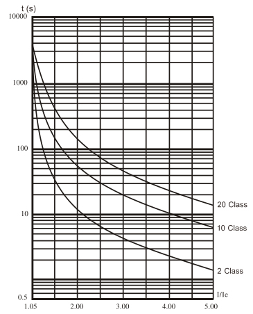
● Start overcurrent protection time: The protection time when it is more than 5 times the maximum operating current of setting item F7 is shown in Table 6.1.
● Running overload protection time: The inverse time limit thermal protection is based on the maximum operating current of setting item F7. The trip protection time curve is shown in Figure 6.1.
● Low supply voltage protection delay time: When the supply voltage is lower than 40% limit value, the protection action time is <0.5s, otherwise the protection action time is <3s when it is lower than the set value.
● High supply voltage protection delay time: When the power supply voltage is higher than the limit value of 130%, the protection action time is <0.5s; otherwise, it is higher than the set value day protection action time <3s.
● Load short circuit protection delay time: <0.1s, the current is more than 10 times the rated current of the Motor Soft Starter.
● Underload protection function of the motor: The protection range is 10%~90% of the rated current of the motor, and the action time is 5~90s. The single digit is multiplied by 10 for the action time. When the single digit is 0, the action time is 5s; the tens digit is the percentage, and protection when the motor current is less than this percentage. This function is prohibited when FU<10.
● The above time parameters are from detecting the valid signal to sending out the trip protection command. The parameter values are for reference only.
● All protection functions of the soft starter can be verified by actual or analog methods. If the user's requirements are not met, special protection devices should be added to ensure safety.
● In order to adapt to different applications, the Motor Soft Starter has five protection levels, 0-basic, 1-light load, 2-standard, 3-heavy load, 4-the best, set by setting item FC:
● The basic protection prohibits the external instantaneous stop terminal function, and only retains the input default phase protection caused by overheat, short circuit and starting. It is suitable for occasions requiring unconditional emergency starting, such as fire pumps.
● The three protection levels of light load, standard and heavy load have complete protection functions, their motor overload thermal protection time curves are different. The motor thermal protection time parameters are shown in the table.
● The best protection has stricter protection standards at start-up, and the other protection function parameters are the same as the standard protection settings.
● Input default phase protection delay time: <3s.
● Output default phase protection delay time: <3s.
● Three-phase unbalance protection delay time: <3s. Based on the current deviation each phase is greater than 50%±10%, when the load current is less than 30% of the soft starter's nominal rating, the reference deviation will be increased.
● Start overcurrent protection time: The protection time when it is more than 5 times the maximum operating current of setting item F7 is shown in Table 6.1.
● Running overload protection time: The inverse time limit thermal protection is based on the maximum operating current of setting item F7. The trip protection time curve is shown in Figure 6.1.
● Low supply voltage protection delay time: When the supply voltage is lower than 40% limit value, the protection action time is <0.5s, otherwise the protection action time is <3s when it is lower than the set value.
● High supply voltage protection delay time: When the power supply voltage is higher than the limit value of 130%, the protection action time is <0.5s; otherwise, it is higher than the set value day protection action time <3s.
● Load short circuit protection delay time: <0.1s, the current is more than 10 times the rated current of the Motor Soft Starter.
● Underload protection function of the motor: The protection range is 10%~90% of the rated current of the motor, and the action time is 5~90s. The single digit is multiplied by 10 for the action time. When the single digit is 0, the action time is 5s; the tens digit is the percentage, and protection when the motor current is less than this percentage. This function is prohibited when FU<10.
● The above time parameters are from detecting the valid signal to sending out the trip protection command. The parameter values are for reference only.
● All protection functions of the soft starter can be verified by actual or analog methods. If the user's requirements are not met, special protection devices should be added to ensure safety.
● In order to adapt to different applications, the Motor Soft Starter has five protection levels, 0-basic, 1-light load, 2-standard, 3-heavy load, 4-the best, set by setting item FC:
● The basic protection prohibits the external instantaneous stop terminal function, and only retains the input default phase protection caused by overheat, short circuit and starting. It is suitable for occasions requiring unconditional emergency starting, such as fire pumps.
● The three protection levels of light load, standard and heavy load have complete protection functions, their motor overload thermal protection time curves are different. The motor thermal protection time parameters are shown in the table.
● The best protection has stricter protection standards at start-up, and the other protection function parameters are the same as the standard protection settings.
The different protection class and thermal protection time set by FA are shown below:
The motor current set by FP cannot be lower than 15% of the soft starter's nominal current. When the current set by the FP is small, the sensitivity error of the protection tripping action will increase.The motor thermal protection trip time curve according to IEC60947-4-2 is as follows:
Power-on Running
READY is displayed at power-on, and the ready indicator is on. Press the start key to start the motor.
Enter FP according to the rated current value on the motor label.
After starting, check whether the motor's rotation direction is correct and the operation is normal. If it is not normal, press the stop key to stop or cut off the power if necessary.
If the starting state of the motor is not ideal, refer to the soft starter's starting mode and application to select the appropriate starting mode.
If the starting torque of the motor is not enough, the starting voltage (in voltage mode) or the current limiting value (in current mode) can be changed to increase the starting torque of the motor.
After the Motor Soft Starter is energized, do not open the top cover to avoid electric shock.
During the power-on test running, if abnormal phenomena such as abnormal sound, smoke or odor are found, should cut off power quickly and find out the reason.
If the fault indicator is on and ErrXX is displayed after power-on or at startup, the cause can be found by the fault code displayed.
Press the stop key or the external control stop key to reset the fault status.
Note: When the ambient temperature is lower than -10°C, it should be warmed up for more than 30 minutes before starting.
Fault and treatment method are as follows:
Note: When the Motor Soft Starter starts the motor successfully, the running status indicator in the middle of the panel lights up, indicating that it is in bypass operation. If the bypass contactor does not pick up and the motor stops running, check the bypass contactor and related wiring for errors or poor contact.Startup Mode and Application
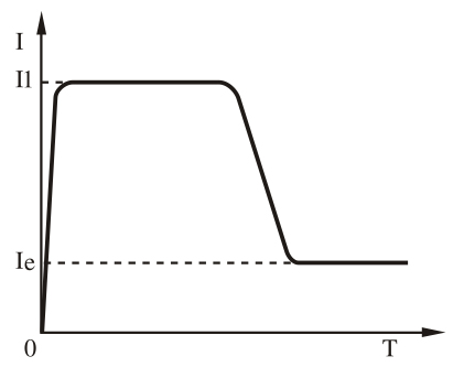
Current limiting start mode
Set the start mode to this mode when setting item F9 to 0.
The current change waveform of the motor with current limiting start mode is given. II is the set starting current limit value, when the motor starts, the output voltage increases rapidly until the motor current reaches the set current limit value II, and the motor current is kept not greater than the value, and then the motor gradually accelerates with the output voltage increasing gradually. When the motor reaches the rated speed, the bypass contactor pulls in and the output current rapidly drops to the motor rated current Ie or below, and the starting process is completed.
When the motor load is light or the setting current limit is large, the max current at startup may not reach the setting current limit.
The current limiting start mode is generally used occasions where there is a start current is strictly limited.
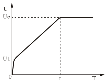
Voltage ramp start mode
Set the start mode to this mode when setting item F9 to 1.
Figure 7.2 shows the output voltage waveform for voltage ramp start. U1 is the initial voltage at starting. When the motor starts, the output voltage of the soft starter rises to U1 immediately after the motor current does not exceed 400% of the rated value, and then the output voltage is gradually rising according to the set starting parameters, and the motor increases steadily with the rise of the voltage, when the voltage reaches the rated voltage Ue. When the motor reaches the rated speed, the bypass contactor pulls in and the starting process is completed.
The starting time is the control parameter obtained under the standard experimental conditions according to the standard load. The RMR1-700 series soft starter uses this parameter as the reference, by controlling the output voltage, the motor is accelerated to complete the starting process, the motor can be accelerated smoothly to complete the starting process. And instead of mechanically controlling the time, no matter whether the motor speed is stable. In view of this, when the load is light, the starting time is often less than the set starting time, so long as it can be started smoothly.
The voltage ramp start mode is suitable for occasions where the starting current is not strict and the start-up stability is demanding.
Jump start mode
Set the start mode for this mode when setting item F9 to 2 or 3.
The output change waveform of the jump start mode is given in the following figure. In some heavy load situations, this starting mode can be chosen when the motor can not start because of the influence of static mechanical friction. When starting, a high fixed voltage is applied to the motor for a limited period of time to overcome the static friction force of the motor load to cause the motor to rotate, and then start by limiting current or voltage ramp.
Before using this model, the motor should be started with non sudden jump mode. If the motor can not rotate because the static friction is too large, this mode should be selected. Otherwise, this mode should be avoided to reduce the unnecessary impact of large current.
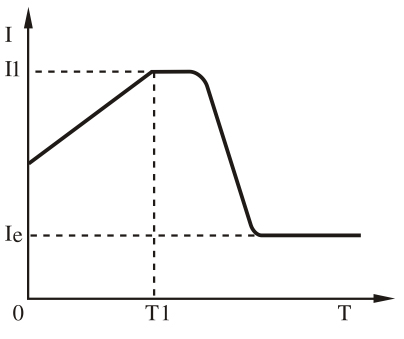
Current ramp start mode
When the setting item F9 is 4, the start mode is set to this mode.
The right picture shows the output current waveform of the current ramp start mode, II is the current limit value set by F6 and T1 is the time value set by F1.
The current ramp start mode has a strong acceleration capability and is suitable for two-pole motors, which can shorten the start-up time within a certain range.
Voltage limit double closed loop start mode
Set the start mode to this mode when setting item F9 is 5.
Voltage-limiting current double-closed-loop start mode adopts voltage ramp and current-limit double closed-loop control. It is a comprehensive starting mode that requires a smooth start and strict current limit. It adopts the prediction algorithm for estimating the working state of the motor.
The output voltage waveform of this start mode will vary according to the motor and load conditions.
Stop mode and application of soft starter
The Motor Soft Starter has two stop modes, soft stop mode and free stop mode.
Soft stop mode:
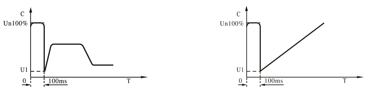
When setting item F2 is not 0, stop mode is set as this mode. In this stop mode, the power supply of the motor is switched by the bypass contactor to the thyristor output of the soft starter. The output voltage of the soft starter is gradually reduced from the full pressure, so that the motor speed is smoothly reduced to avoid mechanical shock until the motor stops running. The output cut-off voltage at soft-stop is equivalent to the initial voltage at start-up.
Soft stop mode reduces and eliminates the surge of pump loads.
In soft stop mode, the soft stop current limit value can be set by the setting item FL to reduce the high current surge during soft stop. The soft stop current limit value is calculated as a percentage based on the start current limit value.
Free stop mode:
When setting item F2 is 0, stop mode is set as this mode.
In this stop mode, the soft starter immediately cut off the bypass contactor and prohibits the voltage output of the soft starter thyristor after receiving the stop command, and the motor gradually stops according to the load inertia. In the case of one-to-two (multiple) wiring, the soft starter's stop mode should be set to this to avoid default phase fault report during output switching.
Under normal circumstances, if there is no need for soft stop, free stop mode should be selected to extend the service life of the Motor Soft Starter.
The free-stop mode completely disables the instantaneous output and prevents transient high-current surges in special applications.
Examples of parameter settings under different load conditions are shown in table. The data in the table are for reference only and should be adjusted accordingly.

view and download
| File name(Click to view) | File type | file size | View times | Click to download |
Product related news
| News title | Promulgator | Release time | View times | Click to read |