


Parameters
Details
Size&weight
Related
Video
Message
Product Overview
GW4-27.5 electrified railway Outdoor Disconnector is outdoor high voltage electrical equipment with frequency of 50Hz, to change in the AC 27.5kV contact network high voltage circuit under no-load condition, and for electrical isolation of the high voltage bus, circuit breaker, and other electrical equipment which are overhauled and high voltage line. It can also be used to open and close low capacitance current and inductance current.
Model and meaning

Normal operating conditions and installation conditions
Altitude is not more than 4700m.
Ambient temperature: upper limit +40℃, lower limit -40℃.
The wind speed is not more than 35m/s.
Does not apply to places with flammable substances, explosion hazards, chemical corrosion and vigorous sports.
Insulator contamination grade: Anti-pollution type is class III heavy dirt (salt density 0.3mg/cm²).
Installation site: outdoor concrete monopole pole.
Classification and technical parameters
1. Classification of isolation switches
2. The main technical parameters of the isolation switch
Structure
GW4-27.5T(D)(W) Outdoor Disconnector has the advantages of reliable performance, simple structure, flexible installation method, easy maintenance, wide application range, and strong versatility.
GW4-27.5T Outdoor Disconnector is a high-voltage electrical appliance composed of unipolar isolation switch, and it is a basic unit derived from other structures. Hereinafter, it is called the common type isolation switch.
GW4-27.5T (D) Outdoor Disconnector is made by installing the grounding knife on the common isolation switch, which consists of once operation type and secondary operation type, hereinafter referred to as the grounding type isolation switch.
GW4-27.5T(D)W Outdoor Disconnector switch is based on common type (grounded type) isolation switch and it is changed from ordinary rod type isolation switch insulator to anti-pollution rod type post insulator, suitable for heavy pollution or high altitude area.
Isolation switch structure
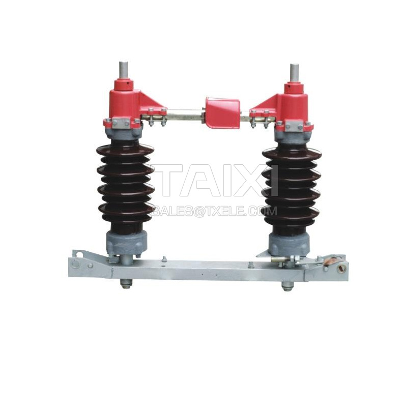
The unipolar isolation switch is respectively fixed on the same underframe by two rod-type post insulators, and is double-column horizontal rotary structure. The outline structure is shown in the figure.

Each pole isolation switch consists of a base, insulator supporter and conductive parts.
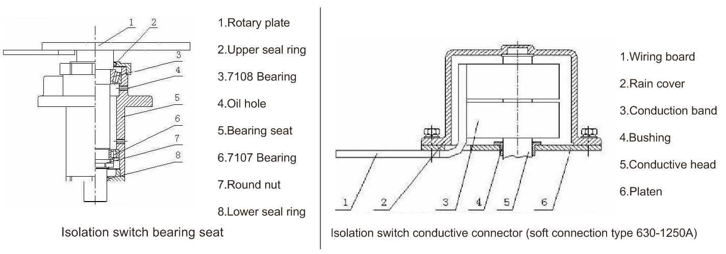
Each pole isolation switch has two insulator supporter fixed on the bearings at both ends of the base (Figure 2) with connecting rods. Each insulating pillar can be rotated horizontally with a 90° rotation angle. The insulating pillars are equipped with conductive sockets, left and right contacts. The left and right contacts are contacted through the conductive tube between the two insulating pillars.
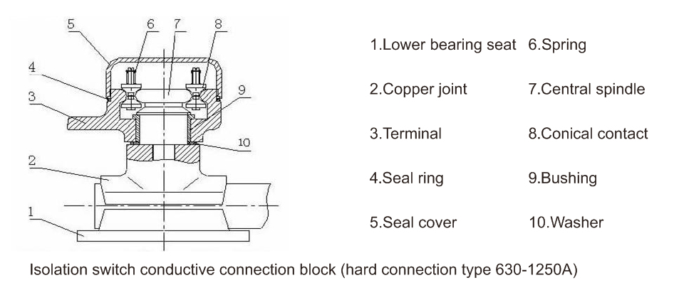
Conductive terminal blocks are divided into two types according on the structure, hard-connected (Fig. 3a) and connection type (Fig. 3b), they are determined according to the user's ordering requirements.
The material of the main circuit is copper. When the rated current is 630A, the surface of the conductive part is tinned. When the rated current is more than 1600A, the surface of the conductive part is silver-plated.
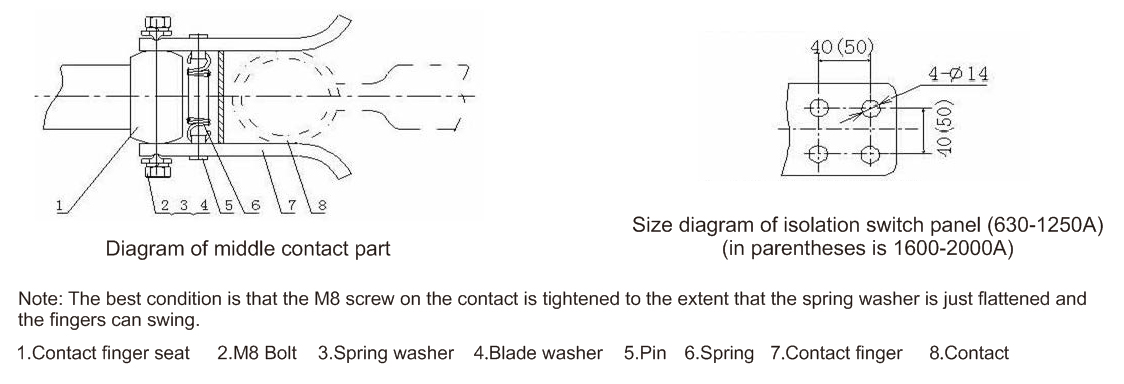
The middle contact is a "handshake" structure. Its structure is pressed by the touch finger washer of the patent technology. It is high pressure, self purification, contact pressure of touch finger remain unchanged for a long time. The touch finger spring has no current and is safe and reliable for a long time.
Different current specification products have the same structural type, base and pillar insulators, but the main conductive circuits are slightly different.
The mechanical interlocking part of the grounding secondary operation isolation switch and the grounding blade is realized by the interlocking disk on the CS8-6D type manual mechanism.
3. The structure of the manual mechanism
This series of isolation switches is equipped with CS11 (ungrounded and single grounding one operation transmission type) and CS8-6D (single grounding secondary operation transmission type).
4. CS11 (see figure) and CS8-6D type manual mechanism (see figure), the operating handle is horizontal rotation, rotation angle is 90 °.
Action principle
The opening and closing actions of this series of isolation switches are basically the same.
1. Operation principle of isolation switch
(1) Without grounding knife type
The operating mechanism of the isolation switch is connected to the active stage of the isolation switch by the connecting pipe. The main shaft of the mechanism is rotated by 90°, which drives the insulating pillar of the active stage to rotate 90°. At the same time, the other side of the insulation pillar rotate in the opposite direction by the connecting rod to realize the opening and closing. to combine the unipolar switches into two-pole or three-pole interlocking switches by the connecting rods, usually unipolar.
(2) One operation type with grounding knife
With grounding knife switch structure is based on the above-mentioned switch structure, increase the operation of the ground drive mechanism. It ensures that the grounding knife start to rotate when the main knife starts to open; when the main knife rotate to the opening position, the ground knife knife also arrives at the ground position. That is, the main and the ground knife complete their respective opening-closing actions separately.
(3) Secondary Operation Type with Grounding Knife
This structure uses the two handles to operate the main knife and the grounding knife respectively. The interlocking device is provided between the two operating handles to prevent misoperation, and to ensure that the program is performed according to the specified procedure (main open-ground close-ground open-main close).
2. Operation principle of grounding switch
The handle of the operating mechanism is rotated 90° horizontally, and the grounding knife is driven to rotate by the connecting rod to realize the action of opening and closing the grounding switch.
3. The auxiliary switch in the operating mechanism is connected with the main shaft of the mechanism, and the corresponding contact is on or off during the opening and closing operation, and the corresponding opening and closing signal is issued.
Installation and adjustment
1. Installation and adjustment of disconnector should meet the following requirements
When using manual mechanism, the general operator should be able to perform the opening and closing operations independently and the action is flexible.
The closing synchronous value of the bipolar or tripolar linkage of the disconnector is: no more than 6mm.
The circuit resistance of the isolation switch should meet the following table
2. Installation and adjustment of isolation switch
The each pole isolation switch is fixed on the horizontal base.
The operating mechanism is placed under the rotating spindle of the active side of the isolation switch, when the main shaft operated by the isolation switch and the mechanism are in the closing position, connect and fasten the water gas pipe with the tooth type hoop. When the main and driven insulation prop is not synchronized, the positive and negative tooth screw can be adjusted to achieve the opening and closing.
The installation and adjustment of the closing synchronism of the double pole or linkage of the isolation switch, when the two terminals bear the normal busbar tension, adjust the length of the positive and negative connecting rod to meet the above requirements.
When the isolation switch is in the closing position, the contact points on the contact should be all contact, the best state for the fastening degree of the M8 screw is that the spring washer just flattened and the finger can swing.
3. Installation and adjustment of secondary operation type grounding knife
When the ground switch knife and the main shaft of the mechanism are in the closing position, the water gas pipe is connected and fastened by the gear type hoop.
When the grounding switch is in the closing position, the contact position of the contact can be adjusted by the position of the ground contact on the conductive pipe. When the closing position is correct, tighten the fastening nut again.
Acceptance and storage
1. After the product arrives at the destination, the user shall place it in a dry and ventilated place. It should not be reversed and it shall be checked and accepted as soon as possible according to the following items:
First, check whether there is any damage or abnormality on the outer surface of the packing box. After the appearance check is completed, open the packing box and take out the attached file.
Check whether the documents attached to the product are complete (including packing list, product certification, installation instructions, etc.).
Remove the product and its accessories (be careful not to damage the insulating pillar ceramic bottle) and check it.
Check whether the products appearance is damaged and abnormal.
2. After acceptance of the product, whether or not it is installed and used immediately, it shall be stored under the following conditions:
The friction parts of the isolation switch must be wiped and coated with acid-free petrolatum.
When the product is stored in the warehouse for a long time, it should be checked regularly (not more than six months). If rust is found, the rust layer should be removed and coated with a rust inhibitor.
Instructions
1. Before going into operation, a full inspection should be carried out and no mistakes before it can be put into operation.
Whether the size of the isolation switch meets the requirements.
The bolts of each connecting part should be firmly fastened, especially with the busbars.
All contact points on the contact should be in contact.
2. Pay attention to the following items after putting into operation:
In general, disconnector must be opened or closed after the circuit load is cut off.
The disconnector with secondary operation type grounding blade, the grounding switch must be closed after the isolation switch is completely opened; otherwise, the closing operation of the isolation switch can be performed after the grounding switch is fully opened.
3. The Outdoor Disconnector must be maintained regularly and overhauled regularly. The following items must be observed during maintenance:
Whether the isolation switch porcelain vase is damaged, whether the glue is loose.
When the disconnector is in the closing position, whether the contact points on the contact are in good contact; whether the spring on the contact is deformed, whether the tension is changed, and the circuit resistance is measured.
Whether the auxiliary switch and other components in the mechanism are well insulated.
Whether the grounding conditions are good.
Whether the rotation parts are flexible and stuck or not.
Please inform the manufacturer of problems found during operation or maintenance.

view and download
| File name(Click to view) | File type | file size | View times | Click to download |
Product related news
| News title | Promulgator | Release time | View times | Click to read |